ฝากข้อความ
เราจะโทรกลับหาคุณเร็ว ๆ นี้!
ข้อความของคุณจะต้องอยู่ระหว่าง 20-3,000 ตัวอักษร!
กรุณาตรวจสอบอีเมลของคุณ!
ข้อมูลเพิ่มเติมช่วยให้การสื่อสารดีขึ้น
ส่งเรียบร้อยแล้ว!
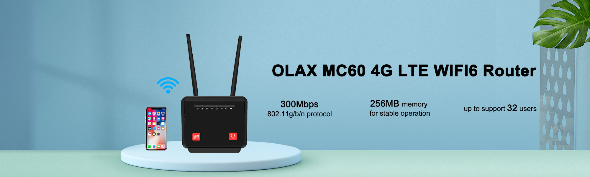
มาตรฐานการส่งสัญญาณ Wi-Fi: 802.11b
ช่องใส่ซิมการ์ด: ช่องใส่ซิมการ์ด 1 ช่อง
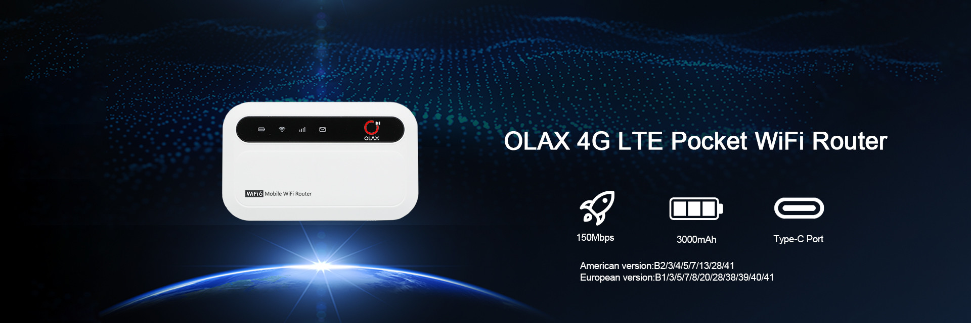
ประเภทสินค้า: MIFI Wifi เราเตอร์
สถานะสินค้า: สต็อค
ความถี่: B1/3/5/8/20/38/40/41 WCDMA:B1/5/8
4G LTE: ใช่
ดูอัลแบนด์: ใช่
อัตราการเข้าถึงอินเทอร์เน็ต: 150Mbps
Max. สูงสุด LAN Data Rate อัตราข้อมูล LAN: 300Mbps
มาตรฐานและโปรโตคอล: Wi-Fi 802.11g, Wi-Fi 802.11b, Wi-Fi 802.11n
ความถี่ที่รองรับ Wi-Fi: 2.4G
อัตราการรับส่งข้อมูล Wi-Fi 2.4G: 150 Mbps
อุปกรณ์แบ่งปัน Wifi: 32 ผู้ใช้ WiFi
สภาพ: 100% ใหม่
การใช้งาน: กลางแจ้งและที่บ้าน
เอฟดีดี: B1/3/7/8/20/28/38/40 /41
สถานะสินค้า: สต็อคพร้อมใหม่
ประเภท: ไร้สาย
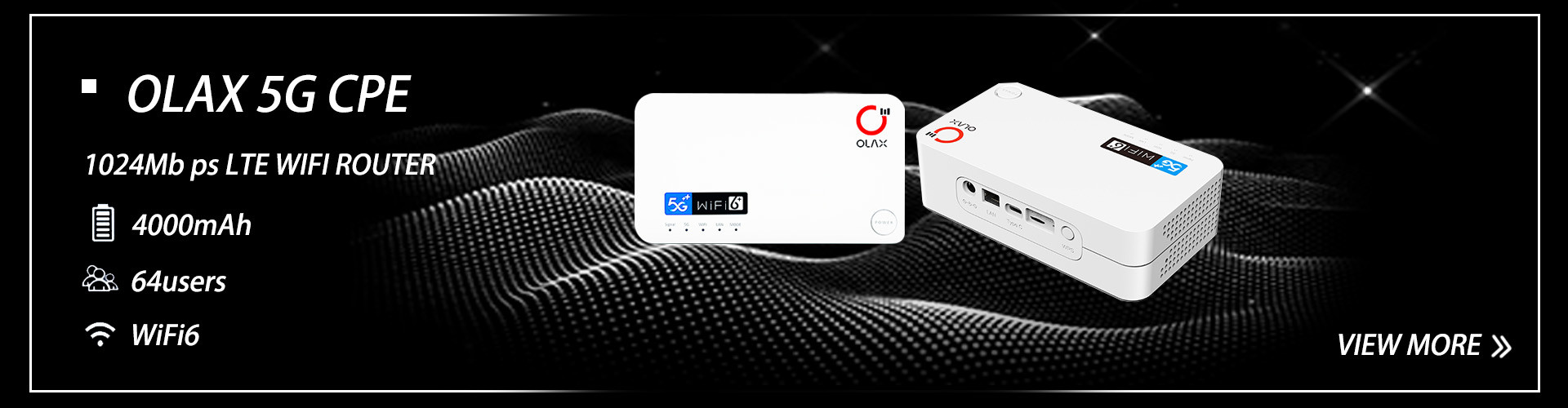
มาตรฐาน: 802.11b/G/N
เสาอากาศ: รองรับหนึ่งพอร์ต
Max. สูงสุด LAN Data Rate อัตราข้อมูล LAN: 1900Mbps
ด้วยฟังก์ชันโมเด็ม: ใช่
ความถี่ที่รองรับ Wi-Fi: 2.4G และ 5G
มาตรฐานและโปรโตคอล: Wi-Fi 802.11g, Wi-Fi 802.11b, Wi-Fi 802.11n, Wi-Fi 802.11ac, Wi-Fi 802.11a, Wi-Fi 802.11ax
0
2026
12/31
12/30
12/29